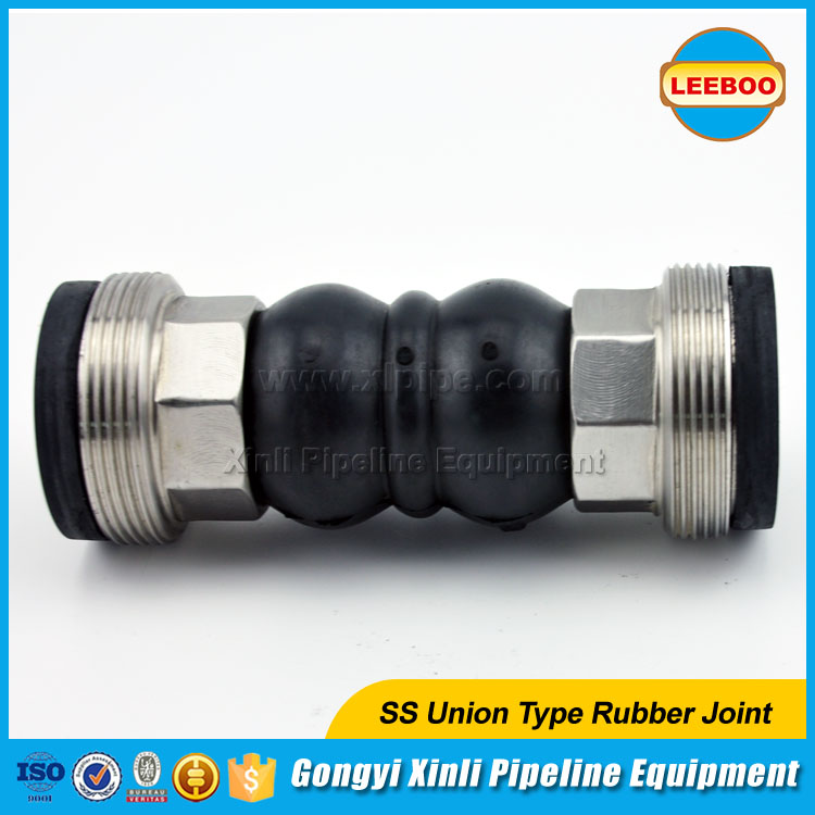
Installation, Operation & Maintenance Manual of rubber expansion joint
Installation, Operation & Maintenance Manual of rubber expansion joint
Verify System Parameters:
Check the system design parameters to ensure the supplied expansion joint meets the requirements of the system and that the
system requirements do need exceed the maximum rated capabilities of the supplied expansion joint. (Pressure, Temperature,
Fluid, expected system movements, etc.)
3.2 Pipe Anchoring/Supports:
3.2.1 Anchoring:
Solid anchoring is required wherever the pipeline changes direction, and expansion joints should be located as close as
possible to anchor points. If anchor points are not used, the pressure thrust may cause excessive movements and damage the
expansion joint.
Note: If the piping system is not properly anchored or anchoring is in
question then the use of control units are required to handle the pressure
thrust loads experienced across the expansion joint.
3.2.2 Supports:
Check the piping supports where the rubber expansion joint will be installed.
Piping to and from the location of the rubber expansion joint must be properly supported and guided to ensure that the
weight of the piping is not transferred to the expansion joint.
Figure 4: Anchored/Supported System
3.3 Pipe Alignment:
Inspect the system for alignment as stated in the procedures listed below for Axial, Lateral, Angular and Torsional
alignment. Piping misalignment in the system should not exceed a maximum of ±1/8” per Fluid Sealing Association (FSA). If
the maximum allowable misalignment is exceeded, the piping should be corrected before installation of the expansion joint
takes place.
Note: Expansion joints can be constructed with a misalignment built in, contact Proco Products, Inc. for additional
information at 800-344-3246.
Figure 5:
Axial Misalignment
3.3.1 Axial Alignment:
To measure for axial misalignment, measure from the inside of one mating flange to the inside of the other, the area in
which the expansion joint is to
be installed. This measured dimension should correspond to the ordered expansion joint’s face-to-face dimension otherwise
an axial misalignment is indicated.
3.3.2 Lateral Alignment:
To measure for lateral misalignment in a concentric reducer system a level or angle square is needed. Use the level or
angle square to make a level baseline from the top of the large end flange and measure the distance from the level or angle
square to the edge of the small end flange as shown as the measured dimension in Figure 6. Repeat this measurement for
several locations around the flange. Any variation in the measurements will indicate a lateral misalignment for a
concentric reducer set up.
To measure for lateral misalignment in an eccentric reducer system a level or angle square is needed. Measure the
difference in the heights from the top of the large end mating flange to the reducer end mating flange. Also take the same
type of measurement in the 6 and 9 o’clock positions of the mating flange. Any measured height in the top position other
than the difference in the standard flange O.D. dimensions will indicate a lateral misalignment. For the measurements taken
at the 6 and 9 o’clock position any difference in the measured heights indicates a lateral misalignment.
3.3.3 Angular Alignment:
To measure for angular misalignment between mating flanges in a concentric or eccentric system the distance from mating
flange to mating flange will need to be measured. Measure the perpendicular distance from the inside surface of one mating
flange to the corresponding inside surface of the other mating flange. Take several of these measurements in various
positions around the mating flanges. Any variation in the measured dimensions indicates that the mating flanges are not
parallel and are angularly misaligned.


Leave Messages: